The main objective of this work package is the design and construction of a modularized functional demonstrator. The demonstrator will have a total power of > 60 kWe derived from batteries and fuel cells; of which 60 kWe will be from fuel cell unit and the battery will have 20 kW power output. The second aim is to connect the developed genset demonstrator to the low voltage electrical grid (400VAC) and operate it for 3 months, while the emissions will be measured under different load scenarios.
6.1 WP Leader
MAN Energy Solutions (MAN)
6.2 Tasks and Outputs
Process, mechanical and electrical design + component procurement
- The modularized functional demonstrator is subdivided into two physical unit systems. One system consists of a battery and main controller container and is provided by MAN Energy Solutions (MAN), while the second system which includes the SOFC system is provided by SolydEra SPA (SE_SPA). Rheinisch-Westfälische Technische Hochschule Aachen (RWTH) developed a control strategy for dynamic power distributing to fuel cells and batteries based on the work in WP5 - Control Strategy and Grid Connection.
- More specifically, MAN Energy Solutions (MAN) has the role of the battery integrator providing the associated process, mechanical and electrical design. The 20-feet MAN ES battery container consists of a battery rack system, power electronics units for stabilization of the DC busbar voltage level and a programmable logic controller (PLC), as shown in Figure 1. The battery container also includes the real time PC provided by (Rheinisch-Westfälische Technische Hochschule Aachen (RWTH) and the hardware platform for the strategy of energy management system (EMS Strategy). Read more here.
 Figure 1: Battery system, power electronics units (two middle photos), EMS and the control cabinet incorporating the Human Machine Interface (HMI) of the MAN ES battery container (from left to right)
- SolydEra SPA (SE_SPA) already delivered the fuel cell system to DLR Stuttgart. The SOFC system consisting of the 40x 1,5 kW SOFC stacks and the required balances of plant (BOPs) (including the gas compressor) and providing the associated process, mechanical and electrical design of the fuel cell unit. Read more here
- Lloyd’s Register EMEA (LR) supports the process by providing safety regulations in the maritime field that can be applied to the design concept.
- Deliverable D6.2 - Drawings and layout for Design on Battery Container – completed
- Deliverable D6.3 - Drawings and layout for the design of FC Cabinet – completed
Battery container manufacturing, assembly and software programming
- The manufacturing, assembly and software programming of the battery container was carried out by MAN Energy Solutions (MAN) in cooperation with subcontractors. This task includes the set-up of control cabinets, power electronics and programming of the control system based on MAN Energy Solutions (MAN)
- The battery container is further interconnected with the fuel cell cabinet via a common 600V DC busbar system.
- Moreover, the battery container includes an energy management system unit (EMS), which is responsible for power distribution calculation between the available hybrid power sources.

Figure 2: Battery and main controller container
Demonstrator site preparation
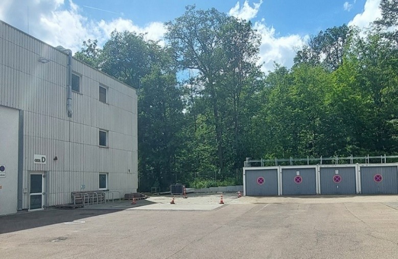
- For the installation and operation of the modularized battery and fuel cell functional demonstrator at DLR premises a location was prepared with all interfaces and connections. Read more here

Figure 3: Demonstration site at DLR Stuttgart (June 2024)

Figure 4 : Test site plan
Installation and operation of demonstrator
- After manufacturing and assembling of its parts, the modularized functional demonstrator will be completed at DLR premises in the end of August 2024, when the battery and main controller container will be delivered to DLR premises in Stuttgart.
- Installation and commissioning of the battery container was carried out by MAN Energy Solutions (MAN) with support of Deutsches Zentrum für Luft – und Raumfahrt (DLR) and SolydEra SPA (SE_SPA).
- The commissioning and installation of the fuel cell container was carried out by SolydEra SPA (SE_SPA) with support of Deutsches Zentrum für Luft – und Raumfahrt (DLR). DLR is responsible for all grid connections (e.g. gas, electricity). The SOFC unit was delivered to DLR Stuttgart in July 2024.

Figure 5: SOFC unit for the demonstrator located at DLR Stuttgart
- After completion of all parts the modularized system will be operated by the Deutsches Zentrum für Luft – und Raumfahrt (DLR) for 3 months, tested under various load profiles. Emission measurements will be carried out by the expert team from Lund University (ULUND). During the operation, the demonstrator will supply the electricity produced to the local electrical grid of Deutsches Zentrum für Luft – und Raumfahrt (DLR).

Figure 6: Demonstration site (October 2024)
Fuel cell testing on inclination pod
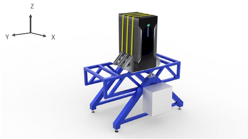
- Testing of a 1.5 kWe solid-oxide fuel cell unit on an inclination pod was implemented by Technische Universiteit Delft (TUD) in close cooperation with SolydEra SPA (SE_SPA) and Lloyd’s Register EMEA (LR) in order to identify potential influences and effects of the exposure of the fuel cell unit to marine conditions: inclinations, ship motions and vibrations were examined.
- The concept design of the experiment is shown below in Figure 7 and Figure 8.

Figure 7: Concept design of the inclination experiment

Figure 8: Real testing at SolydEra premises in Italy
Watch the video
- Deliverable D6.1 - Safety report on the tests of fuel cell unit on the inclination pod – completed
6.3 Duration and Status
- Months 7 - 54
- Status – in progress
- MS11 – List of specifications – completed
- MS12 – Technical drawings – completed
6.4 WP6 Highlights
- Design, construction, installation, and operation of a modularized functional demonstrator consisting of a Solid Oxide Fuel Cell-Unit and a Battery container (including a battery rack system, power electronics units, a main controller and an energy management system (EMS), in other words the real-time PC).
- Connection of the modularized functional demonstrator to the local low voltage 400VAC electrical grid (at DLR site) and its operation for 3 months.
- Testing of a fuel cell unit on an inclination pod (simulating the behaviour of a SOFC unit under rough sea conditions).
- Battery Container: all required parts (container, battery system, power electronics, etc.) were procured, the internal software was programmed. The Battery Container was physically assembled in March 2024 and will be transported to the Deutsches Zentrum für Luft – und Raumfahrt (DLR) premises in August 2024.
- SOFC-Unit: tests with the reduced-power SOFC Unit were successfully completed, the 60kW SOFC Stack Unit system was completed and delivered in June
- Demonstrator Site Preparation: the test site on Deutsches Zentrum für Luft – und Raumfahrt (DLR) premises was finalized and ensure alignment with all necessary connections, interfaces, and safety regulations for both SOFC and Battery Container
6.5 Next Steps
- Installation and Operation: The installation completed by the end of August 2024. Currently, the operation of the demonstrator is scheduled with a detailed execution plan. Furthermore, a test protocol has been drafted regarding the power profiles to be tested, including edge cases, normal operation modes, stepwise power load variations, and dynamic tests.
- Emission measurements are planned for one month of testing operations. The required results will then be analysed by the expert team at Lund University. Read more under WP7 description.
Last updated: October 24th, 2024
