
This work package involves the system engineering of the hybrid solid oxide fuel cell (SOFC)-Battery genset, the optimization of the sizing of the SOFC and the battery unit, as well as design validation of the SOFC-Battery hybrid genset in an experimental proof-of-concept (PoC). Finally, the aim of this work package is the development of a virtual genset simulator and an engineering proposal for a multi-MW genset whose integration is realized under WP4 – Ship Integration.
3.1 WP Leader
Deutsches Zentrum für Luft – und Raumfahrt/German Aerospace Center (DLR)
3.2 Tasks and Outputs
Genset process system engineering and validation
- The overall objective of this subtask is to engineer a 5 to 60 MWe SOFC-Battery hybrid genset concept based on key performance indicators (KPI’s) defined in WP2 - Requirement Analysis. The task focuses on the development of a first Process Flow Diagrams (PFD) by Rijksuniversiteit Groningen (RUG), which was complemented in a second iteration by including the SOFC performance characteristics obtained from experimental characterization of the large stack module (LSM) from SolydEra SA (SE_SA), as well as the study of the anode off-gas and cathode off-gas recirculation.
- An optimization of the heat exchanger network and the development of a piping and instrumentation diagram (P&ID) was performed by Ecole Polytechnique Fédérale de Lausanne (EPFL). This development process was done iteratively based on the input of the experimental results and analysis of the Proof-of-Concept (PoC). At this stage of the project, the first PFD, optimization, and P&ID development were refined after the results of testing experiments. In addition, first transient models were developed and validated during the experimental campaign by Deutsches Zentrum für Luft – und Raumfahrt (DLR) alongside the application and parameterization of an energy management system by Rheinisch-Westfälische Technische Hochschule Aachen (RWTH). The final outcome of this task, a complete P&ID and engineering design of the hybrid genset capable of satisfying the requirements defined in WP2 - Requirement Analysis and safety-related requirements, was achieved.
- Concept design reviews to identify applicable regulations and IMO safety codes with respect to integration requirements for different cruise ship designs was performed by Lloyd’s Register EMEA (LR), who additionally performed a high level HAZID workshop to analyse the potential hazards identified by the P&ID in the context of maritime safety standards, in collaboration with WP3 members.
- Deliverable D3.1 – Report on safety and regulatory requirements for large-scale integration of scalable modular gensets on-board cruise ships – completed
Hybrid genset sizing and design
- In this task, the scale advantages for high-power SOFC systems were identified. Current commercial systems were compared with the concept a scalable high-power SOFC unit. The design constraints of a marine SOFC unit were defined in consultation with shipbuilders Chantiers de l'Atlantique (CdA) and Meyer Werft (MW), and marine regulators Lloyd’s Register EMEA (LR). The positive effect of cathode off-gas recirculation to the decrease of needed airflow to the system was also evaluated and included into consideration.
- The design constrains were met by a concept design by Technische Universiteit Delft (TUD) of a 110 kWe SOFC unit containing six approximately 22,5 kWe stacks. Stacks in this unit can be replaced after the degradation of the SOFCs. The visualisation of the unit is in Figure 1.

Figure 1 Concept design of a 130 kW SOFC unit
- Concept design of modular marine SOFC power plant respecting size constraints was completed by Technische Universiteit Delft (TUD) and the control unit was adapted to simulation scenarios by Rheinisch-Westfälische Technische Hochschule Aachen (RWTH).


Figure 2 Render of concept design SOFC room for the SOFC unit with COGR (cathode off-gas recirculation)
- Deliverable D3.2 – Steady state and dynamic operation of the hybrid genset system with unitized control algorithm – pending.
Fuel cell module assembling and operation
-
- Within this task a 30 kWe Large Stack Module (LSM) has been assembled, delivered and the experimental results of the Proof-of-Concept (PoC) were analysed. The LSM in Figure 3 was operated in close collaboration between SolydEra SA (SE_SA) and tests at Deutsches Zentrum für Luft – und Raumfahrt (DLR).
- The characterization of the LSM has been completed. This process involved evaluating the performance and behaviour of the LSM under different conditions. Specifically, two types of conditions were analysed: (i) steady state: (LSM operates under stable conditions) and (ii) transient (LSM operates under changed operational parameters, such as ramping up or down).
- Deliverable D3.3 – Report on the sizing of modular genset and scalability to multi-MW scale – completed.
Hybrid fuel cell + battery PoC build-up and operation
-
- The main objective of this task was to build up and operate the PoC, consisting of the LSM (Figure 3) and the Li-ion battery (Figure 4) together with the adaptation of the control in the Energy Management Unit (EMU) in Figure 5 c). The test rig was set up including power delivery from the LSM and battery at DLR.
- PoC of the SOFC-Battery hybrid in Figure 5 was successfully tested at DLR and the first emission measurements were carried out by Lunds Universitet (ULUND) at SolydEra SA (SE_SA) premises, see Figure 6. Measurements of the emissions produced by a burner were conducted at various operational settings. These measurements were taken using a loop-off method, which involves bypassing the SOFC unit, to allow for more precise or specialized data collection, in order to identify data quality control and postprocessing methodologies in preparation for the emissions measurement at the Genset Demonstrator (WP6).
- Precise emission measurement was realised on the Genset demonstrator (WP6) at Deutsches Zentrum für Luft – und Raumfahrt (DLR) Stuttgart premises by the team of Lunds Universitet (ULUND).

Figure 3 GALACTICA test rig with 30 kWe LSM from SolydEra

Figure 4 Setup of the Li-ion battery at DLR
 LSM, b) Li-ion Battery, c) EMU")
Figure 5 Proof of concept at DLR with a) LSM, b) Li-ion Battery, c) EMU

Figure 6 Experimental Set-Up: Emission Measurements by ULUND at SolydEra
Virtual genset simulator
- The purpose of this subtask is to compile the results of work done in several different tasks to build a so-called Virtual Genset Simulator (VGS) that can be integrated to ship energy system simulators used by Chantiers de l'Atlantique (CdA) and Meyer Werft (MW). The production of the Virtual Genset Simulator in Figure 7 by Teknologian Tutkimuskeskus (VTT) summarized and integrated the results of the modelling tasks and requirements analysis. It is a scalable model that can simulate the performance of the modular, multi-MW SOFC/battery genset system under different dynamic operation requirements based on the ship's energy (electrical and heat) demands. The virtual genset simulator was developed by adopting a programming framework compatible with the different software tools used by the shipbuilders and operators in FMU format (FMI Version 2.0).
- Functional and technical requirements for the first virtual genset model for energy simulations were defined and tested with shipyards, and a model based on a table lookup was produced. Subsequent feedback rounds with shipyards resulted in a quasi-stationary lookup table model parametrized for a number of installed 1-MW units and battery capacity and leveraging the modularity of the SOFC/battery genset in the NAUTILUS concept to provide optimal system-level efficiency across a broad load range (15% - 100%), where active modules operate at maximum efficiency and non-active modules consume power. Finally, emissions measurements results obtained by Lunds Universitet (ULUND) in at the Genset demonstrator in WP6 were used to parametrize the non-CO2 emissions and integrate them as part of the model output.
- Deliverable D3.5 – Virtual genset simulator tool – pending
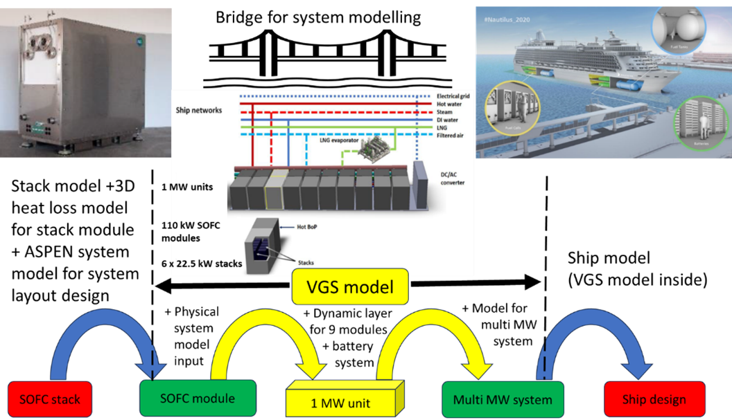
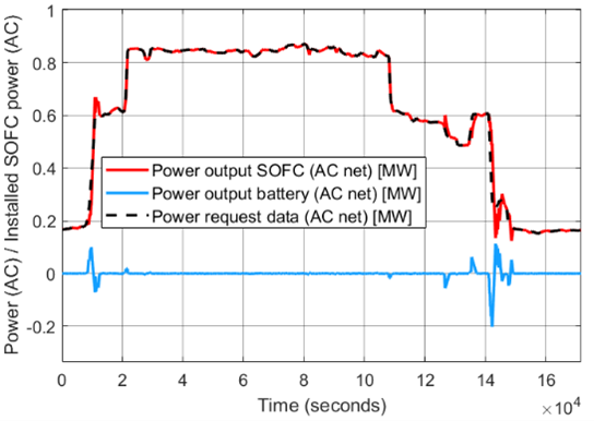
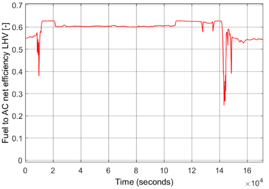
Figure 7: Virtual Genset Simulator role summarizing models developed in the project and bridging the gap from experimental activity to the cruise ship's energy system models (7a above); approach for high efficiency in broad part load range transitions (7b and 7c below).
3.3 Duration and Status
- Months 1 - 54
- Status – in progress
- MS2: P&ID definition and PoC validated hybrid genset - completed
- MS3: Control algorithm in real-time PC - completed
- MS4: PoC operated – completed
3.4 WP3 Highlights
- Proof-of-Concept (PoC) of Solid oxide fuel cell (SOFC) + battery hybrid is successfully tested
- The conceptual design of a 110 kWe SOFC unit to be numbered up within the engine room limitations within a ship is finalized.
- Development of a dynamic model for the SOFC and first validation via experiments, Battery model development, and validation
- Further validation of the dynamic models through the analysis of the transient experiments
- System process flow design based on ASR-expressions from experiments & its optimisation is achieved
- Safety and regulatory requirements for integration of genset in ship is gathered
- HAZID workshop based on the system design was performed
- Completion of the virtual genset simulator and its integration in the ship energy model as the digital twin
- Finalizing of Digital System Design with optimization of electric and thermal energy
- Parametrization and inclusion of the non-CO2 emissions measurements results obtained at the Genset demonstrator into the virtual genset simulator output
3.5 Next Steps
- Activity completed
Last updated: May 28, 2024